APPLICATION
Direct measurement of voltage in High Voltage System
is Not possible because of insulation problem of
measuring instruments. It is also not possible to
use direct voltage for the system protection purpose
due to its high value and high insulation problem
protective relays. Therefore voltage transformers
are used to step-down the high system voltage to low
standard value accurately in proportion to their
ratio.
BASIC
FUNCTIONS OF VOLTAGE TRANSFORMERS ARE
To reduce the line voltage to a value which is
suitable for standard measuring instruments relays
etc.
To isolate the measuring instruments, meters, relays
etc. from high voltage
side an installation.
To sense abnormalities in voltage and give signals
to protective relays to
isolate the defective system.
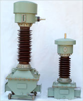
CONSTRUCTION VOLTAGE TRANSFORMER MAINLY CONSISTS OF
:
- Primary
& Secondary winding
- Electromagnetic
Core
- Bottom
Tank & Oil Expansion Chamber
- Porcelain Bushing
PRIMARY &
SECONDARY WINDING :
Copper enameled wire is used for winding. Primary
is wound with multilayer and graded insulation. The
diameter and length of each layer is selected such
that Surge voltage is distributed equally in all
layers of the Winding. Multilayer Kraft Paper
insulation is provided between winding layers.
Stress equalizing shield is provided on last layer
of the winding. H.T. Connection is brought out
through metallic pipe.
Secondary is separately
wound and inserted in the primary winding as per the
requirement. Winding and tapping of V.T. is done in
dust-free atmosphere. |
|
 |
ELECTROMAGNETIC
CORE :
C.R.G.O. Silicon Steel is used for building up
Electromagnetic core. Shell type construction is
used to minimise leakage reactance. |
BOTTOM TANK
& OIL EXPANSION CHAMBER :
Bottom tank and oil expansion chamber are made of
M.S. Sheet. All tanks and chambers are painted with
Oven baked paint, after clearing by seven tank
process.
All surfaces which come in contact with oil are
painted with oil insoluble paint. M.S. parts can be
hot dip galvanised on request. |
|
PORCELAIN
BUSHING :
Brown Glazed Porcelain Bushing with different shed
profiles to suit different pollution conditions is
used. These Bushings are Hollow Cylindrical Type
confirming to I.S. 563/IEC 815. Bushing with collar
at both the ends is clamped using Aluminium Flanges.
Nitrile and Neoprene Gaskets are used at both sides
of collar to form flexible joint. This joint can
sustain vibrations without damaging bushing. Bushing
with Cemented Flanges are also used. |
INSULATION :
High Quality Electrical
Grade Kraft Paper crepe paper is used for insulating
primary and secondary winding of V.T. The high
voltage connection is brought out through paper
condensor formed on metallic pipe using fine grading
of insulation. semi conducting shield is used to
give linear distribution of electric stress along
the length of the bushing. The paper insulation is
dried in oven under very high vacuum and strictly
controlled conditions. Filtered and de-aerated EHV
grade oil is filled in.V.T. while V.T. is under
vacuum. To seal it, the space left for expansion on
the top is filled with dry and pure nitrogen
through non-returnable valve at pre-determined
pressure. |
Testing
Packing & Transportation
Maintenance
HOW TO SELECT
THE V.T. :
It
is important to specify correct parameters of V.T.
while ordering for optimum
design. Following are main
factors for selecting Voltage Transformers.
- SERVICE
VOLTAGE : System Voltage in which V.T. is to be
installed e.g. 11kv, 22kv, 33kv etc.
- INSULATION
: Whether OUTDOOR OR INDOOR
- ATMOSPHERIC
CONDITIONS : Such as condition of Pollution,
Altitude, Ambient Temperature etc.
- INSULATION
LEVEL : If insulation level other than
associated with service voltage is required, it
should be specifically mentioned.
- RATED
PRIMARY VOLTAGE : Rated primary voltage is
generally rated system voltage for unearthed
type V.Ts and rated system voltage divided by
square root of three for earthed type V.Ts the
V.Ts. can be manufactured suitable for more than
one system voltage. In such case, different
primary voltages required may be indicated.
- RATED
SECONDARY VOLTAGE : Standard values of secondary
voltages are 110v or 110v 3 depending on
application of the secondary winding. V.Ts. with
different secondary voltages other than those
mentioned above can be manufactured and
supplied.
- VOLTAGE
FACTOR : All V.Ts are manufactured suitable for
continuous voltage factor 1.2 As per I.S./I.E.C.
Specification, short time voltage factor is
different for different earthing systems.
Therefore appropriate system earthing conditions
may be specified.
- NUMBER OF
SECONDARY WINDINGS, THEIR BURDENS & ACCURACY
CLASSES :
Number of secondary windings, their burdens and
accuracy classes are selected on the basis of
application. Two types of classes are available,
one for metering and other for protection.
Unlike current transformers, accuracy of one
winding is influenced by loading of other
winding. Due to this reason burden of each
winding should be correctly mentioned. Accuracy
of V.T. is guaranteed at the secondary terminals
of the V.T. the impedance of cable connecting
secondary terminals to load (Relay of Meter)
offers series drop in output voltage. The caused
additional errors of cable and is proportional
to the load on the secondary. Therefore, it is
advisable to select separate metering and
protection winding. Alternatively, single
winding can be used for metering and protection
if separate cables are used for connections.
(Cable of 4 sq. mm. cross section offer 2%
voltage drop at 100 meters distance with 100 VA
burden of secondary voltage of 110V/3).
RESIDUAL
VOLTAGE TRANSFORMER :
RESIDUAL
VOLTAGE TRANSFORMER is used to detect unbalanced
voltage in three phase system and to supply voltage
to directional earth-fault relay.
For directional earth-fault
relay, it is necessary that the voltage applied to
voltage coil of the relay corresponds in phase to
that of the current in current coil. Such voltage
will be the Residual voltage of the system and will
be the phasor sum of the three line-to-earth
voltages.
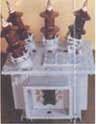
Residual voltage can be
achieved by connecting secondaries of three single
phase V.Ts connected in three different phase, in
open-delta fashion. It is however, economical to use
three phase V.Ts instead of Three nos. single phase
V.Ts 'SE' manufactures three phase P.V.Ts suitable
upto 33kv system voltage.
|