|
APPLICATION
Direct measurement of current in High Voltage System
is Not possible because of insulation problem of
measuring instruments. It is also not possible to
use current flowing through the system directly for
protection purpose due to its high insulation
problem.
BASIC
FUNCTIONS OF CURRENT TRANSFORMERS ARE :
|
 |
1. To reduce the line current to a value which is
suitable for standard measuring
instruments relays
etc.
2. To isolate the measuring instruments, meters, relays
etc. from high voltage
side an installation.
3.
To protect measuring instruments against short circuit currents.
4. To sense abnormalities in current and give current signals to protective relays
to isolate the defective system. |
There are four main factors which
determine the capability of current
transformer i.e.
* Insulation Level (Service
Voltage)
* Rated primary current
* Short time withstand current
* Burden and Accuracy
THE CURRENT TRANSFORMERS MUST :
1. Withstand operational voltage and over voltage in
the network
2. Withstand rated primary current in continuous
operation without exceeding
maximum allowed temperature rise.
3. Be capable o sustain thermal and mechanical
stresses developed due to
system falut current
4. Feed current to external circuit with specified
accuracy at specified primary
currents
|
 |
 |
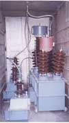
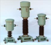
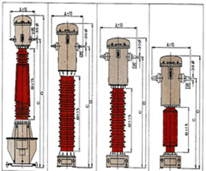
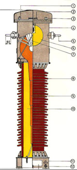
CONSTRUCTION :
Core & Secondary Winding,
Primary Winding,
Insulation,
Procelain Insulators,
Tanks & Bases,
Testing,
Packaging & Transportation,
Maintenance |
HOW TO SELECT THE
C.T.
It is impotant to specify correct
parameters of CT while ordering for optimum
design. Following are main factors for selecting
current transformer.
1. SERVICE VOLTAGE : System voltage in which CT is
to be installed e.g.
11kV, 22kV, 33kV ETC.
2. INSTALLATION : Whether OUTDOOR or INDOOR
3. ATMOSPHERIC CONDITIONS : Such as condition of
Pollution, Altitude
Ambient Temperature etc.
4. INSULATION LEVEL : If insulation level other than
associated with service
voltage is required, it should be
specifically mentioned.
5. RATED PRIMARY CURRENT : Specify rated primary
current / currents (if
required more than one value).
Also indicate if different primary current
is required for different cores.
6. CONTINUOUS PRIMARY CURRENT : Max.primary current
that can be withstood
continuously by current
transformer e.g. 120% of primary current
7. RATED SECONDARY CURRENT : Whether 1 Amp. or 5
Amps.
8. SHORT TIME CURRENT & ITS DURATION : Specify
fault current of the system
in which CT is to be installed
along with its duration. it is most important to
specify realistic value of S.T.C.
as at lower primary current, higher S.T.C.
value neceesitates bulky &
costlier design. Also specify dynamic current if
other than 2.5 times S.T.C. is
required.
9. NO.OF CORES THEIR BURDENS, ACCURACY : Basis of
application, No.of cores,
their burdens and accuracy class
should be specified. It is advisable to specify
minimum required Burden for
metering core as unnecessary high burden will
necessitate bulky and costlier
design. Specified accuracy is guaranteed for
100 %
to 25% of rated burden only. Current transformer offers minimum error
if 75% to 60% burden is connected to secondary, Therefore,
ideally rated
burden higher than 1.5 time actual burden should be
specified. Also, it is
important to specify correct burden in context
of instrument Security Factor
(I.S.F.). The I.S.F. indicates the over
current as multiple of rated current at
which the metering core will
saturate, thus limiting the secondary current
flowing through meter
and protect it from damage. If actual burden connected
is half of the
rated burden, the I.S.F. will increase two-fold of its rated value.
10. KNEE
POINT VOLTAGE, SECONDARY RESISTANCE AND
EXCITATION CURRENT : For
differential protection, R.E.F. Protection, Bus Bar
Protection, C.T. with
accuracy class PS is required. The Knee Point
Voltage,
Secondary resistance and
excitation current should be for this core. It is
always better to specify
Formula for Knee Point Voltage related to relay used
for the protection. This
will help designer to optimise the design.
|